|
|
|
Boiler Systems
|
1. BOILER SYSTEM AND STEAM GENERATION
Boilers heat water to generate steam to be used for a variety of purposes including manufacturing processes, chemical processing, electrical power generation, and heating. (Figure 1.1 shows a typical boiler system.) Fuel sources include:
- Natural gas
- Fuel oil
- Coal
|
- Nuclear energy
- Waste heat
- Wood
|
- Refinery off gases
- Garbage
- Black liquor
|
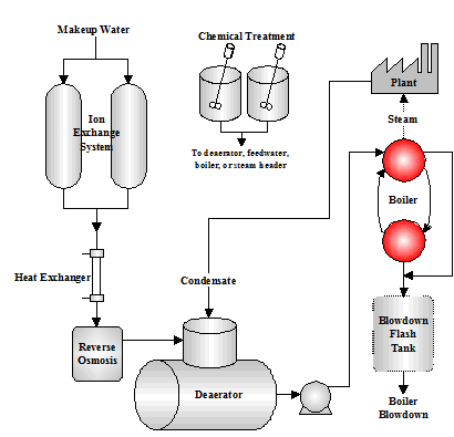
Figure 1.1 Boiler System
Figure 1.1 Boiler System Types
|
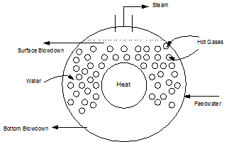
Firetube Boiler (Figure 1.2)
|
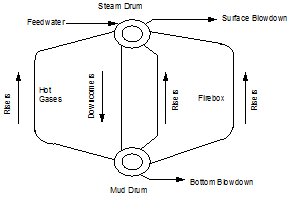
Watertube Boiler (Figure 1.3)
|
|
|
|
Firetube boilers where the hot gases are on the inside of the tubes and water fills the vessel on the outsides of the tubes (see Figure 1.2). Firetube boilers are limited to lower pressures and lower steam flows than can be achieved with watertube boilers.
|
Watertube boilers where water is on the inside of the tubes and the fire and hot gases are on the outside of the tubes
|
1.1 Steam Generation Loop
This section describes the various components in the Steam Generation Loop. Figure 1.4 depicts the equipment used for steam and power generation and heat recovery.
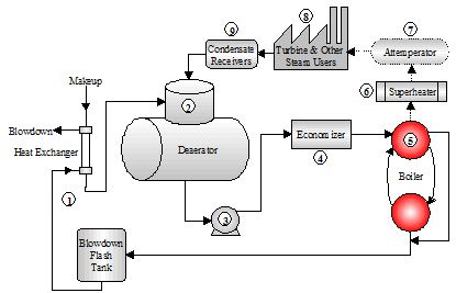
Figure 1.4 Steam Generation Loop
- The starting point selected for the steam generation loop is the blowdown heat recovery equipment. This process employs the use of a flash tank and a heat exchanger that uses heat from the blowdown to heat the cooler boiler makeup water.
The heat energy saved from the blowdown represents the additional heat input that is not required to raise the temperature of the makeup water. The steam from the flash tank can be used for the deaerator or other low pressure applications.
The normal achievable approach temperature (difference between the blowdown and makeup temperatures) is 20ºF. Energy calculations typically use this level of efficiency for determining the savings associated with blowdown heat recovery equipment.
- The deaerator removes dissolved gases that can cause corrosion. The deaerator is also the common return point for condensate. The operating temperature is typically 220ºF or higher. The deaerated feedwater is commonly held in the storage section of the unit for 5 – 10-minutes before being pumped into the boiler.
- The deaerator tank is typically installed 20 - 30 ft. above the feedwater pumps. The feedwater pumps require high suction head pressure in order to remain primed. The discharge force of the feedwater pumps must be great enough to overcome the steam drum pressure.
- The economizer is a bank of heat exchanger tubes which absorbs heat from the rising path of combustion flue gas exiting the boiler and transfers the heat into the feedwater.
A general rule for efficiency gains realized with the operation of an economizer: "Every 40 - 50 degree drop in flue gas temperature results in a 1% gain in thermal efficiency."
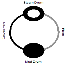 The density and temperature of the boiler water varies at different locations in the boiler (see Figure 1.5). This variance of density creates a circulation of water between the steam drum and the mud drum. The boiler tubes carrying the hotter and rising water are called risers. The tubes carrying the heavier and falling water are called downcomers. Steam bubbles begin to form as the water exits the risers and enter the steam drum. The steam leaving the top of the drum is called saturated steam. The density and temperature of the boiler water varies at different locations in the boiler (see Figure 1.5). This variance of density creates a circulation of water between the steam drum and the mud drum. The boiler tubes carrying the hotter and rising water are called risers. The tubes carrying the heavier and falling water are called downcomers. Steam bubbles begin to form as the water exits the risers and enter the steam drum. The steam leaving the top of the drum is called saturated steam.
- A very dry steam is required for turbines and other plant processes. A superheater is used to remove moisture by adding more heat to the steam. The resulting product is a hotter, more efficient steam that is absolutely dry.
- Attemperation is used to control the temperature of the superheated steam. Direct attemperation uses feedwater or condensate to cool the steam. The liquid is injected into the steam until a temperature monitor downstream of the injection point indicates the proper control. Indirect attemperation routes the steam through a heat exchanger in the boiler mud drum for temperature control.
- The power turbine and plant steam applications are the final components in the steam generation loop. As the steam gives up energy and heat at the point of work, it condenses to the water phase.
- Condensate receiver tanks collect the condensate and return it to the deaerator for reuse as boiler feedwater.
2. PRETREATMENT
Boiler pretreatment equipment is used to remove impurities from water to reduce problems associated with those impurities and to reduce dependence on chemical treatment. Many criteria go into choosing pretreatment equipment.
2.1 Pretreatment System Selection Guidelines
Pretreatment system selection guidelines include; 1) Technical factors such as what impurities need to be removed, 2) Operational factors such as manpower requirements and ease of operation, 3) Costs, 4) Space requirements
|
Some pretreatment systems include:
|
Acid Dealkalization
Electrodialysis (ED)
Electrodialysis Reversal (EDR)
Reverse Osmosis
Sodium Chloride Dealkalization
|
Anthracite Filter
Carbon Filter
Manganese Greensand Filter
Sand Filter
|
Cold Lime Softening
Hot Process Softening
Sodium Zeolite Softening
Split Stream Softening
|
Continuous Deionization (CDI)
Countercurrent Ion Exchange
Demineralization by Ion Exchange
Weak/ Strong Acid Ion Exchange
|
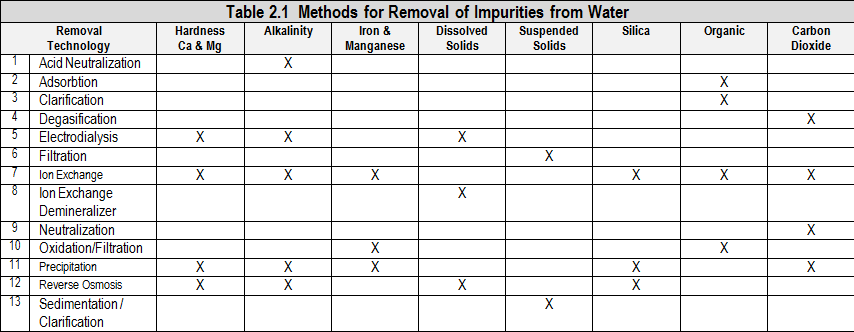
2.2 Softening
When boiler feedwater is hard (containing calcium and magnesium), deposition can occur. This means the boiler must work harder to produce steam which results in wasted fuel, water, and chemicals. The purpose of a softener system is to remove hardness before it enters the feedwater and boiler. This process is called sodium zeolite softening. The softener takes calcium and magnesium and exchanges it for sodium. This process is called ion exchange. An ion is a charged particle in solution. The ion can have a positive or negative charge. Cations are positively charged and anions are negatively charged. The medium of exchange is sodium zeolite resin.
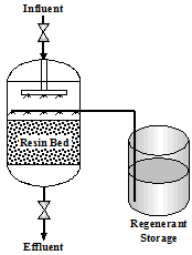
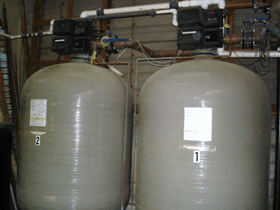
The sodium zeolite resin is cross linked polystyrene plastic bead that holds sodium ions. As water passes through the resin, the beads act as magnets and attract calcium and magnesium cations. This attraction draws these positive ions out of the water onto the resin beads and exchanges them for sodium ions. The water exiting the softener contains positively charged sodium ions and negatively charged anions. Figure 2.1 shows a typical softener setup.
|
Figure 2.1 Softener
|
Figure 2.1 Softener
|
|
|
2.2.1 Service Cycle
The Service Cycle is a continuous flow of incoming water entering the top of the unit through an inlet header. The water passes through the resin bed and exits at the bottom of the tank. There is a constant exchange of hardness ions for sodium ions. When the resin is exhausted, regeneration is necessary.
2.2.2 Regeneration
Softener regeneration typically takes place in four steps as illustrated in Figure 2.2 and described below.
Backwash - The water flow through the resin bed is reversed. The backwash flow lifts and fluffs the resin bed. By placing each bead in motion, suspended solids, broken resin beads, and fines are removed. An excess flow rate can cause a loss of resin beads.
Brining - Brine is a highly concentrated salt solution. The brine rinse flows from the top of the softening unit down through the resin bed and out the bottom to the sewer. The calcium and magnesium ions are shed by the resin beads and replaced by sodium from the brine solution. The brine must be drawn in properly (time, volume, length, and concentration) to assure complete regeneration. Poor contact time can result in shortened service runs.
Slow Rinse - (Displacement) The brine is rinsed from the resin bed at the same flow rate as during the brine rinse cycle.
Fast Rinse - Final traces of brine are rinsed and removed at a faster flow rate. A chloride test can determine adequate rinsing.
2.1 Reverse Osmosis
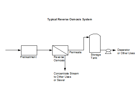
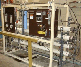
Reverse osmosis (RO) is a very viable boiler pretreatment system since it is becoming more economical and its operation can be relatively simple with proper maintenance. The process uses a pump and a semipermeable membrane. Water is forced through the membrane by the pressure generated from the pump. Pure water passes through the membrane while most of the dissolved solids remain with a concentrated stream. Figure 2.3 shows a typical reverse osmosis system.
|
Figure 2.3 Typical Reverse Osmosis System
|
|
|
3. DEAERATION
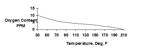
Deaeration is an efficient way to remove dissolved gases from boiler feedwater to reduce the corrosion potential of the water. The amount of oxygen dissolved in water decreases as temperature increases. The remaining dissolved oxygen will still cause the water to be aggressive and can lead to localized pitting in the pre-boiler system.
|
Figure 3.1 Solubility of Oxygen in Water with Changing Temperatures at Atmospheric Pressure
|
|
3.1 Deaeration Design
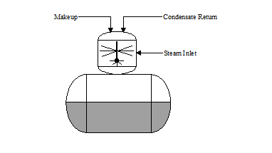
There are two sections in a deaerator. The deaerating section and the storage section. The dissolved gases are stripped from the water through a combination of steam, heat, and mechanical separation in the deaerating section. The deaerated water flows to the storage section where it is held as boiler feedwater.
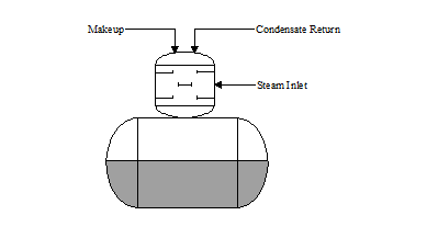
There are two basic types of deaeration designs: “tray type” and “spray type”. In the "tray type" deaerator (see Figure 3.1), water is directed or sprayed through distribution pipes into a steam space. The hot steam increases the temperature of the water to within a few degrees of saturation steam temperature. Dissolved gases are stripped and vented to atmosphere.
TRAY: The water cascades down several "trays" in the tray section. The cascading flow breaks the water into fine droplets, permitting greater steam contact. This action further scrubs the dissolved gases from the water. The deaerated water flows into the storage section where a blanket of steam maintains a few pounds of pressure on the system.
SPRAY: In the "spray type" deaerator (see Figure 3.2), the steam and water scrubbing action is similar to the tray deaerator except the water is broken up with spray nozzles inside the deaeration section. The spray nozzles should be inspected annually to ensure they are not obstructed or corroded.
Proper venting is essential. Typically, an 18-36 inch steam plume should be visible. Deaerators should reduce dissolved oxygen down to 5-10 ppb. The deaerator dome water temperature should be within 4ºF of the steam temperature at the operating pressure and the storage section should be within 5ºF of the steam temperature at the operating pressure. If makeup and condensate are mixed prior to the deaerator, corrosion resistant piping such as stainless steel should be used.
|
Figure 3.2 "Tray Type" Deaerator
|
Figure 3.3 "Spray Type" Deaerator
|
|
|
3.2 Oxygen Scavengers: The deaerator is not 100% efficient, and trace amounts of oxygen will remain in the deaerator effluent. Remaining dissolved oxygen can cause pitting in the feedwater piping, economizer, or boiler, so an oxygen scavenger is used to chemically remove the residual oxygen. Catalyzed sodium sulfite is the most common oxygen scavenger used. Sulfite reacts with oxygen to form sodium sulfate. The sulfite and oxygen reaction is as follows: (2 Na2 SO3 + O2 -> 2 Na2 SO4)
The ratio of sodium sulfite to dissolved oxygen is 7.88 to 1. In high pressure boilers, total dissolved solids concentration in the boiler water is critical. For these applications, a volatile scavenger is used that will not contribute solids to the boiler water. The optimal feed point for oxygen scavengers is the storage section of the deaerator. The contact time for a complete chemical reaction is an important consideration. If feedwater is used for spray attemperation or desuperheating, the take-off point should be carefully selected. Sodium sulfite adds dissolved solids to the feedwater and the sodium can lead to caustic embrittlement to the steam lines. The desuperheater take-off point should be located upstream of the chemical feed line.
4. INTERNAL TREATMENT: The purpose of an internal chemical treatment program is to ensure the boiler systems are kept clean and protected from the remaining contaminants not removed by external treatment. Internal treatment serves to protect the boiler system from deposition and corrosion, and to minimize carryover. Some of the impurities of concern in the feedwater include hardness, alkalinity, silica, iron, copper, oil, grease, and process contamination. Compounds can build up on heat transfer surfaces (boiler tube) and cause an insulating effect that reduces heat transfer. In extreme cases, the overheating of the boiler tubes can cause a failure of the tube wall. The reduction in heat transfer efficiency results in an increase in the fuel-to-steam ratio and increased fuel costs. Another result of scaling is a decrease in water circulation. Steam surging, overheating, and drag caused by deposits alter circulation patterns which wastes fuel. Lower boiler water flow will increase the rate of deposit formation. The internal treatment chemicals designed for scale and deposit control include phosphates, chelants, and polymers.
4.1 Phosphate: Phosphate treatments are referred to as precipitation programs. Phosphate is used in the boiler water to precipitate (force out of solution) calcium hardness. The resulting calcium-phosphate sludge is a non-adherent compound that is more easily dispersed. In the presence of sufficient hydroxide alkalinity, calcium-phosphate becomes a fluid, hydroxy-apatite type precipitant. This reaction is preferential to the formation of calcium carbonate, calcium sulfate, or other scale forming precipitates because calcium phosphate is more insoluble and will precipitate in the water rather than directly onto boiler surfaces. Polymeric dispersants can then "condition" the sludge, keeping the particles small to be more easily removed by blowdown. Magnesium is precipitated with hydroxide and silica and dispersed by the polymer.
4.2 Chelants: Chelant based programs are referred to as solubilizing treatments because the calcium and magnesium are kept in solution. Chelants are weak organic acids that complex calcium and magnesium into the structure of the organic molecule. The entire molecule remains in solution, preventing deposit formation. The most common form of chelant is EDTA. Competing anions are ion compounds in the boiler water that can limit the ability of chelants to complex contaminants. Boiler feedwater must be of highest quality for the best results with a chelant program. Overfeeding chelants can lead to corrosion problems. Since chelants may solubilize iron, there is a potential for corrosion if the chelant is grossly overfed or if it is fed when oxygen has not been totally removed. Chelant dosages must be properly controlled and fed into the boiler feedwater, usually on the pressure side of the feedwater pump and through a stainless steel injection quill.
4.3 Polymers and Dispersants: Polymers are added to boiler water to enhance the capabilities of phosphate and chelants. The polymer provides dispersing and solubilizing action for iron and hardness. Early dispersants were tannin and lignin compounds. These materials modify crystal growth and form soft sludges with the hardness. Today, synthetic polymers such as polyacrylates, polymethacrylates, polyacrylamides, and many others are commonly used. Performance of these compounds is far superior to natural organics. Proper dosages are key to results. The polymers add a negative charge to suspended solids, causing them to repel each other and remain dispersed. Polymers can also minimize the actual formation of some suspended solids.
4.4 Anti-Foams: Anti-foams are used to reduce carryover, especially if the carryover is caused by chemicals, alkalinity, and total dissolved solids. The anti-foam affects the steam bubble wall, causing it to burst at the steam/water interface. The result is a reduction in foam formation and a reduction of boiler water being carried into the steam.
5. BOILER BLOWDOWN: Blowdown is performed to maintain boiler water dissolved solids within proper operating limits and to remove suspended solids. Blowdown can also reduce the amount of carryover.
Continuous blowdown is generally removed from the steam drum of a watertube boiler or near the surface of a firetube boiler.
Manual or bottom blowdown takes place in the mud drum of a watertube boiler or from the bottom of a firetube boiler. The concentration of solids is heaviest at these locations. The control of both continuous and manual blowdown is important for maintaining good waterside results in a boiler system.
Boiler blowdown is frequently cooled in a blowdown flash tank. The flashed steam is either vented or it can be used in the plant's low pressure steam system. Heat from the hot blowdown water can be used to preheat the makeup water by using a heat exchanger. A boiler blowdown procedure is included in Boiler Appendix A.
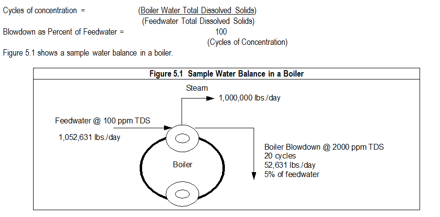
5.1 Calculating Cycles of Concentration and Blowdown Percentages: Cycling is the term used to describe the concentrating effect of solids remaining in the boiler water as pure water exits as steam.
6. STEAM PURITY AND STEAM QUALITY: Steam is evaporated water. The purity of steam and condensate should be very high and can be determined by the total dissolved solids content of a properly collected sample. Sodium analyzers can also be used to monitor steam purity. The process of solids escaping from the boiler and into the steam is called carryover. Steam separators and baffles in the steam drum are designed to impinge the steam as it rises out of the drum to remove moisture which contains the dissolved solids. There are two causes of carryover; mechanical and chemical. Some of the mechanical causes of carryover are:
- Excessive movement of water in the steam drum.
- Spray or mist carryover from fine water droplets. This usually occurs when separation devices are missing or damaged.
- Steam production in excess of design rating.
- Sudden swings in steam load.
- High water level.
- Changing boiler pressures.
Chemical carryover:
- Foaming caused by grease, oil, high solids or alkalinity.
- Selective silica carryover. At pressures > 600 PSIG, dissolved silica will vaporize with the steam. This is especially critical where turbines are in operation.
- High chemical concentration in the boiler water.
Steam quality is a measure of moisture in the steam. "Wet" steam is less efficient & can damage equipment in the system.
7. CORROSION: Boiler corrosion can occur for several reasons. Two causes are low alkalinity and low pH, or oxygen in the water.
Acid corrosion is a general thinning effect on metal areas, or pitting under extreme conditions. The common method for elevating pH is the addition of caustic or soda ash. Most operating testing procedures will include ranges for "P", total "M", or "OH" hydroxide alkalinity.
Oxygen corrosion results in deep pitting in localized areas. It can begin in the deaerator storage tank and feedwater if the deaerator is not adequately removing dissolved oxygen. Oxygen corrosion can also occur very rapidly in the economizer and boiler steam drum.
Catalyzed sodium sulfite is the most commonly used oxygen scavenger. Others are available for high pressures or specialized applications.
Caustic embrittlement is stress corrosion cracking that can occur to boilers. Three factors create an environment for caustic embrittlement to occur; 1) Leakage of boiler water and flashing steam around a point where two pieces of metal come together, 2) Concentrated hydroxide alkalinity in the boiler water, 3) High stress and fatigue of the metal at the point of leakage and area of concentrated hydroxide alkalinity. The chemical treatment solution for caustic embrittlement involves the use of sodium nitrate. This form of corrosion is much less common with more modern boiler designs and much improved chemical treatment.
Caustic corrosion is a form of corrosion that occurs most normally in high pressure boilers when caustic concentrates locally at 1-40%. A coordinated phosphate treatment program uses mono, di, or trisodium phosphate to control pH and hydroxide which minimizes the risk of caustic corrosion.
8.0 CONDENSATE RETURN LINE SYSTEM: As steam releases heat, a phase change occurs from vapor to liquid. The water is commonly referred to as condensate. The most cost effective use of condensate is to recycle (reclaim) it as boiler feedwater. This cost savings is measured in the heat content of BTUs. (One BTU equals the amount of heat necessary to raise one pound of water one degree Fahrenheit). Also, as more condensate is returned, less makeup water is required, creating a water cost savings. Condensate contains constituents that can cause corrosion; 1) carbon dioxide (carbonic acid), 2) oxygen, 3) possible process contamination.
Carbon dioxide (CO2) is formed when the carbonate and bicarbonate alkalinity in boiler water break down from the heat and pressure in the boiler. Oxygen is introduced from leaks in the return line system and open condensate receivers, or from the feedwater. Oxygen attack typically occurs in the form of localized pitting.
8.1 Carbonic Acid Attack: CO2 in steam is not corrosive. When the steam cools and turns to water (condensate), the CO2 reacts form carbonic acid (CO2 + H2O -> H2CO3). The pH of the condensate drops and the water becomes corrosive. This type of corrosion causes grooves in the bottom of the return lines. The dissolved and suspended corrosion products are brought back to the boiler system which can lead to iron and copper deposits in the boiler and deaerator.
An effective solution for improving condensate quality can be achieved with a condensate polisher. Polishers are filters which operate like the ion exchange equipment in the pretreatment area. Polishers can remove suspended metal oxides and some dissolved solids. Backwashing and regeneration are required to maintain the polishers.
Condensate may be dumped if the iron or dissolved solids concentration becomes excessive.
8.2 Chemical Treatments: Volatile amines are compounds that volatilize with the steam and leave the boiler. Portions of the amine condense with the condensate at varying temperatures and pressures.
8.3 Neutralizing Amines: Neutralizing amines elevate the pH of the condensate by neutralizing carbonic acid. The feedrate of the amine is adjusted to maintain the pH of the condensate in a non-corrosive range (8.0 - 9.0). The dosage of the amine changes with fluctuations in steam production and feedwater alkalinity, or carbon dioxide levels in the steam. A return line product can be a blend of one or more amines. The blend formula depends upon system pressure, temperature, metallurgy, and complexity of the condensate system. Some common amines are: morpholine, cyclohexylamine, and diethylaminoethanol (DEAE).
8.4 Filming Amines: Filming amines are compounds that protect metal surfaces by laying down a thin film of material on the inside of the return line pipes. The dosage of filming amines is based solely on steam production. "Filmers" have the capability of protecting systems from carbonic acid and oxygen attack. If fed improperly, filming amines can cause gunking. The excess product in the system accumulates in steam traps, pipe elbows, and low flow areas. Proper feedrate and feed point location is important with a filming amine program. Filming amines should be fed directly into the steam header with a stainless steel injection quill. The product should be mixed with hot condensate or feedwater. The dilution water should be alkaline, (pH > 7.0) with a low total dissolved solids concentration. A combination of filming amine and neutralizing amines may be used. The pH elevation by the neutralizing amine can reduce acid attack and allow better filming. Also, the neutralizing amine may help distribute the filmer.
8.5 Corrosion Coupons: The most effective method of monitoring condensate corrosion is the installation of metal coupons. The corrosion coupons should be placed at locations throughout the return line system that will adequately determine proper distribution and protection being provided by the amine treatment.
|
|
The material provided in this bulletin is informational in nature and is not intended to be instructions for a particular location or installation. There is no guarantee, warranty or other assurance of fitness of purpose or operational performance or results either express or implied. The user assumes all risk in following the information provided. Always read and follow product safety and performance instructions on product labels, Material Data Safety Sheets and those provided specifically for your requirements by your ServeTech representative.
|
|
ServeTech Water Solutions, Inc. - Wheaton, IL - www.servetechwater.com - info@servetechwater.com - 630-784-9050
|
|
|